The other day, wanting to give shape to an idea I had, I created something like this ↓.
ARKitを使ったリモートタッチパッドの実験。精度がまだ荒いけど基本的には上手くいってる。#ue4 #arkit pic.twitter.com/Kt5E5fPCQn
— ayuma (@ayuma_x) December 26, 2019
When you trace your finger over the iPad, a line is drawn on the display inside the iPad, but when you remove the iPad, the same line is drawn on the actual display.
This might be confusing at first glance, but actually, nothing is added to the iPad side display. Only the camera feed is shown on the iPad’s display.
What Did I Want to Do?
A while ago, I was creating AR content using an iPad for work, and that’s when I thought, “I want to think about uses for AR other than [overlaying some display].”
I’m sure someone has probably done something similar to what I did this time, but I tried it because “there’s meaning in thinking up and shaping ideas yourself.”
In this experiment, the iPad is used as an input device. The idea is to create a remote touch display by skillfully using ARKit’s image detection and object detection features.
Things to Do
I’ve summarized the things that need to be done to shape this idea below.
This time, the iPad application is built based on UE4 (4.24)’s Handheld AR Blueprint template.
- Know the position and angle of the display shown on the iPad
- Know the position of the finger touching the iPad as relative coordinates on the display
- Send coordinates from the iPad to the PC side
- Draw lines on the PC side according to the sent coordinates
Know the position and angle of the display shown on the iPad
First, we need to know the position of the display.
I considered two methods for knowing the position: “marker method using images” and “object detection,” but this time I chose object detection.
I wrote an article before about how to use object detection with UE4+ARKit, so please take a look if you’re interested.
Using ARKit’s Object Detection Feature in UE4 - AYU MAX
First, I tried creating detection data by scanning the display, but the display’s shape had few feature points, and I couldn’t get satisfactory results.
So, I created detection data for the cluttered area next to the display and decided to determine the display’s position and angle based on the relative position from that point.
Naturally, this method breaks down if the positional relationship with the display changes.
↓ Scanning process
Knowing the display’s position and angle after scanning is exactly as described in the previous article mentioned above.
Know the position of the finger touching the iPad as relative coordinates on the display
Next, let’s think about how to know the position of the finger touching the iPad.
In the implementation within the UE4 AR template used this time, there is logic (WorldHitTest function in BP_ARPawn) to check if there is an Actor at the touched point.
I thought about tweaking this to know the display’s position.
First, prepare a flat mesh that is the same size as the real-world display and place it in the level. This mesh doesn’t need to be visible, so I applied a transparent material.
Next, on every Tick, move this mesh to the position and angle where ARKit detects the real display.
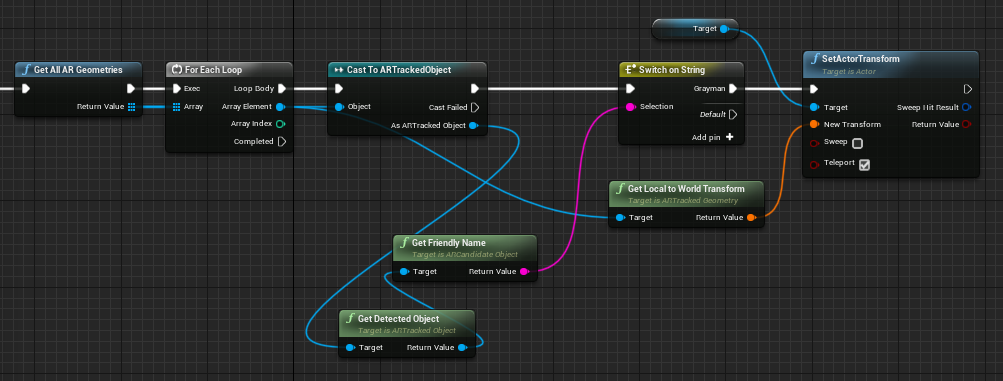
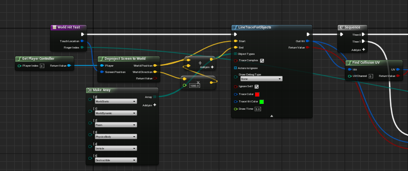
Next, looking inside the WorldHitTest function, you can see that the LineTraceForObjects node is used.
LineTraceForObjects can determine if there is a 3D object between two specified points.
Combining this node with the Deproject Screen to World placed just before it allows identifying the 3D object placed at the touched location from the screen coordinates (x, y) on the iPad when touched.
Using this mechanism, we can determine whether the mesh placed earlier is being touched by a finger.
However, what we want to know this time is where on the display is being touched, so we need more detailed information.
Therefore, I tried adding a part that feeds the value returned by LineTraceForObjects into Find Collision UV.
This allows us to get information down to which part (UV coordinates) of the surface of the touched 3D object.
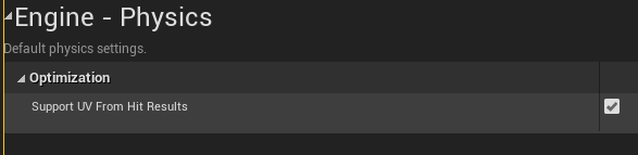
- To use
Find Collision UV, you need to checkSupport UV From Hit Resultsin Project Settings. (Turning it ON probably increases processing load)
Send coordinates from the iPad to the PC side
We will send coordinates from the iPad to the PC (Windows) via socket communication (UDP).
We use ObjectDeliverer for UDP transmission. For ObjectDeliverer, please see past articles.
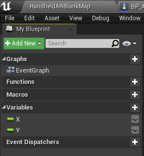
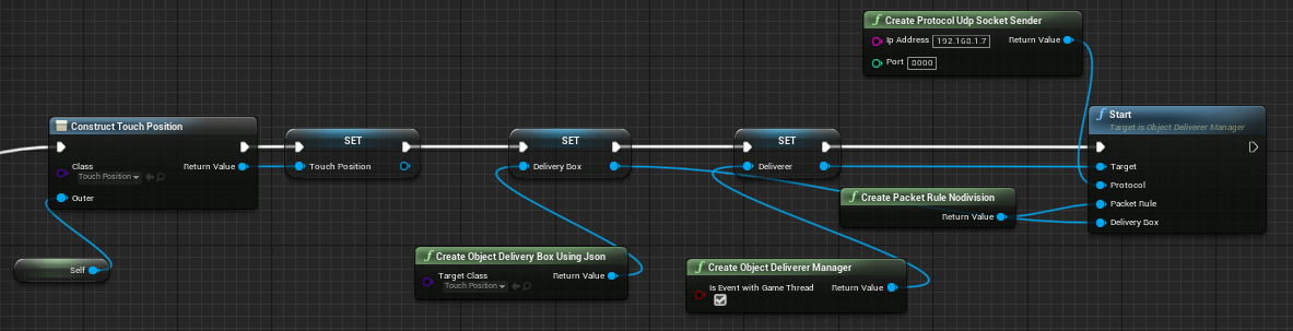
First, create a container for sending. It’s simple, just define a Blueprint like the one below. I named the object TouchPosition. Only variables for X and Y coordinates are defined.
Initialize ObjectDeliverer to send this object.
↓ Like this.
And at the place where the UV of the flat mesh is obtained with Find Collision UV, send the coordinates to the PC using UDP as follows.
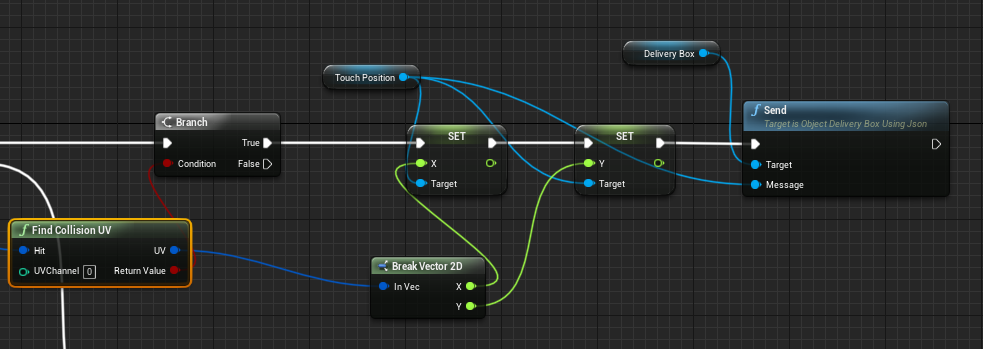
With this, every time the display shown on the iPad is touched, the coordinates of where on the display is being touched are continuously sent to the PC.
Draw lines on the PC side according to the sent coordinates
The PC side isn’t doing anything complicated; it just receives UDP using ObjectDeliverer, extracts the sent X, Y coordinates, and then draws lines using UMG.
This part is not crucial this time, so I’ll omit it.
Thoughts After Trying It
I was able to achieve the movement exactly as I had thought.
Although nothing other than the camera feed is displayed on the iPad, I was able to create something interesting by utilizing ARKit’s features. I feel that this kind of usage holds various possibilities.
I’ll try to shape new ideas when they come up.